Configuration
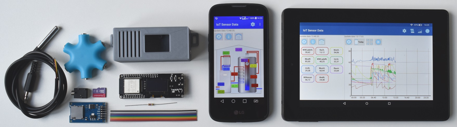
The board is configured with a browser. The firmware uses the Basecamp Library, a library written especially for IoT projects with the ESP32. Enter the ip address or the network name for instance TempLogger.fritz.box in the browser. The ip address is displayed on the oled display after the start of the board.
If the board isn’t configured yet, it is in Access Point Mode and has opened a hot spot called ‘ESP_xyz’. In this case, the computer have to connect to the Wi-Fi ‘ESP_xyz’. The IP address in this case is the 192.168.4.1.
If the board is unable to connect to the configured Wi-Fi after switching on, the Wi-Fi settings will be reset after 5 attempts. After that, the board is back in access point mode. After two more failed attempts, all configured data will be deleted.
Example of a configuration:
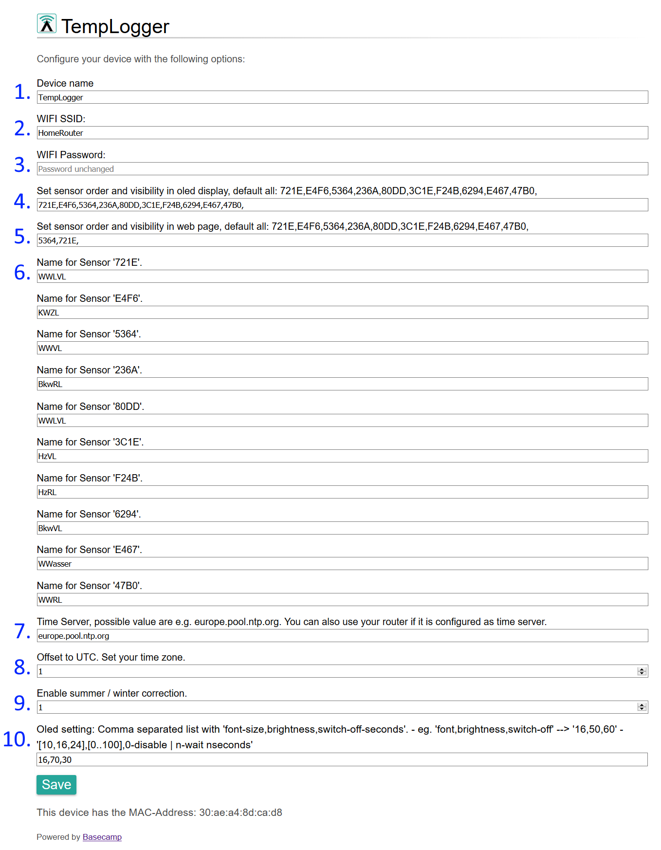
- The device name of the ESP32 board. The Fritz Box uses the name as network name, for instance TempLogger.fritz.box
- The name of the Wi-Fi network to which the ESP32 board should log in.
- The password for the Wi-Fi network.
- Here it is configured which sensor values are displayed in which order in the OLED display. The line consists of a comma-separated list of sensor Id’s. If, for example, Only the values of the WWasser (the sensor E467) and HzVL (the sensor 3C1E) are to be displayed, then ‘ E467,3C1E, ‘ is entered there. Then the value on the display is for WWater and the second value is for HzVL. Depending on the font size, 2 to 4 lines of text fit into the display. If more sensors are to be displayed, the display rotates. The text after ‘default all:’ is the default value for this configuration and can be copied if you want to see all sensor values.
- Here it is configured which sensor values are displayed in which order in the Android application. The line consists of a comma-separated list of sensor Id’s. In this way, contiguous values such as heater supply and heater return temperature can be represented one after the other. The text after ‘default all:’ is the default value for this configuration.
- The name of the sensor as shown in the OLED display and in the Android application. Too long names are cut off in the Oled Display.
- Another time server can be entered here. The right time is important to ensure that the sensor values get the right time stamp.
- This is where the time zone is entered. For Berlin, that would be +1.
- Here it can be determined whether a summer and winter time change should take place.
- Here, the font size for the sensor values is determined. With the font size 24, 2 lines of text fit on the display. With font size 16 it is 3 lines and with font size 10 it is 4 lines.
With SAVE, the values are written on the board. The board then executes a reboot.