Replica
If the items have not yet been purchased, you can here have a look on the BOM and the online shops.
ESP32 Board Test
Turn on the board. For this purpose, a 5V, 1A power supply with Micro USB connector can be used, as it is used to charge mobile phones.
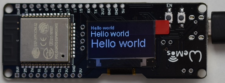
Then download and flash the ESP32 test application. Now it is ensured that the board is OK and can be flashed.
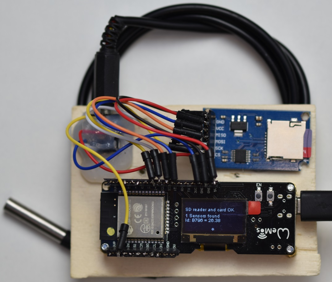
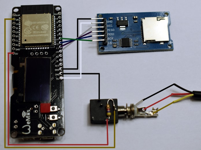
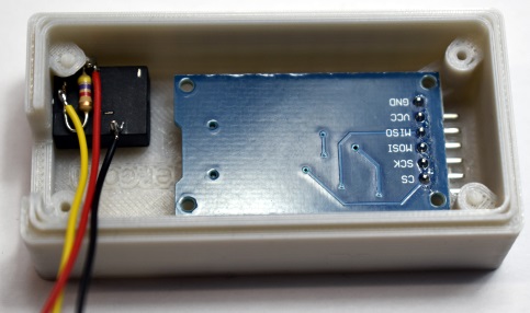
Connect ESP32 board to Flash Card board
Cut and tin the pins of the SD Card Board. Cut the 6 cables for the connection between SD Card Reader and ESP32 Board to 10 cm. Remove the insulation and tin them and connect the two boards together as specified in the schematic. Then plug in the Micro SD card and turn on the board. If everything works, the message ‘SD reader and card OK’ appears. The SD Card must be formated with FAT32. If there are problems, it’s best to use other older FAT32 formatted SD cards and/or use the ‘official’ SD card reader.
Prepare 3.5 inches jack plug
Then soldered the jack with the 4.7 KOhm resistance. Then cut 3 cables to 10 cm, strip the insulate and tin the cables and combine the jack plug and the esp32 board. The two unused contacts can be cut off. The 4.7 KOhm are the standard value for the pull-up resistance. If many sensors are used, bigger than approx. 6 pieces and there are problems, the resistance can also be reduced, e.g. By parallel switching of another 4.7 KOhm resistance. I’m using a 4.7 KOhm resistance with 11 sensors with 2.5m cables each.
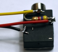
Connect the sensor to the stereo jack
Connect the 3 cables of the sensor ground (black), voltage (red) and data (yellow) according to the image and assemble the plug. Connect the plug to the board and turn on the board.
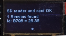
When everything works, the sensor ID and temperature are displayed. Now the plug can be screwed up again and the contacts can be insulated from each other (with hot glue). The ID, for example, ‘B796’ is the sensor’s ID. In this way, several sensors can be connected in parallel and still differentiated from each other. This is now repeated for the desired number of sensors. Multiple sensors can be connected to each other via one or more audio splitters.
Sometimes i had the problem that no sensor was detected, especially when several sensors were switched in parallel. These were all contact issues. I have connected 11 sensors with 2.5m cables each and use a 4.7kOhm pull-up resistance. Short line lengths are probably optimal, whereby the sensors are interconnected one after the other (as a bus).
Warning: The jack plug should only ever be plugged or pulled at power-free ESP32 board.
Temperature logger application flashing
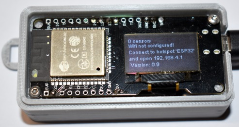
Then download and flash the ESP32 Temperature Logger application. The display should look like this.
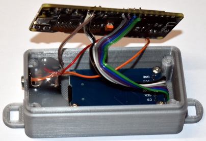
Place into the case
When everything works, the jack plug can be built into the case and fixed with hot glue. The SD Card Reader is installed with the top face down and fixed with 3 screws. Then install the ESP32 board.
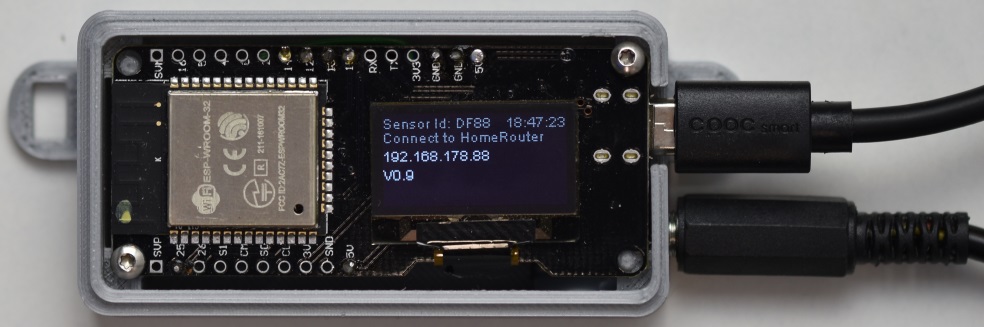
Configuration
With the Temperature Logger firmware, the board now has its WIFI functionality. An unconfigured board does not yet have access to the router and in this case it is in access point mode. After configuring the WIFI SSID and the WIFI password, it connects to the router after a reboot. The board can then be reached on the network.
This means:
The ESP32 board is in access point mode with the SSID ‘ ESP _ xyz ‘. The laptop must then be connected to the ‘ESP_xyz’ network. Then call the IP address 192.168.4.1 in the browser. The configuration page of the board appears. The routers SSID and the router password are entered and stored with the Save button. The board reboots and logs into the router. Now the board is accessible on the network. With the Fritz Box, for example, this works with esp32Temp.fritz.box. When starting the ESP32 board, you will also see the board’s current IP address. More information on how to set the individual parameters can be found here.